


EARTH CONNECTION IN THE CAR
TIPS FOR "CLAMP 31"

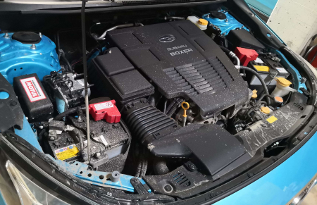
The main focus is on all areas and components outside the passenger compartment (vehicle interior), such as the battery, alternator (generator), glow plugs/spark plugs, starter (starter motor), the entire ignition and injection system and engine electrics/electronics.
But don't forget the ABS and headlight system!
In the entire automotive sector, the earth potential is the vehicle body. A conductive part, practically the entire vehicle, is also the return conductor for the vehicle electrical system - each consumer only requires one line.
Start the fault diagnosis.
A fault diagnosis normally always begins with a check of the power supply. Often too little attention is now paid to the opposite connection, i.e. earth to the battery, engine or body. However, this is just as important! Minor soiling of connections and joints with negative effects is sufficient. The formation of contact resistances can lead to high quiescent/creeping currents and blatant voltage drops. This results in various malfunctions, trouble with starting difficulties due to a discharged battery and subsequently misdiagnoses. This can even happen in a specialist workshop when reading out the fault memory and interpreting it correctly with an OBD diagnostic device!
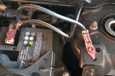
Ground connection, always use a clean, bare metal point - away from the battery, for example.
Therefore, check earth connections regularly for tightness and cleanliness. These must always be bare metal, clean and free from oxidation, dirt and rust. Special contact sprays are commercially available to protect against moisture and corrosion. Furthermore, visually inspect all eyelets and plugs at the cable ends and the cables. These may have become loose over time due to shaking, vibrations and temperature fluctuations. In the worst case, water that has penetrated the cables, e.g. due to an engine wash, can lead to internal corrosion and the associated problems.
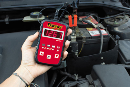
It is high time to check the resistance with a load tester (multimeter) and measure the voltage drop (ideally under load).
This check and any further work is best carried out by specialised workshop personnel.
PS: In cars, the earth is labelled "clamp 31" in all wiring diagrams for all manufacturers and is always connected to the negative terminal of the battery. Please note! In all modern cars, the battery sensor is also fitted to the negative terminal.
Here is a list of all clamps in vehicle wiring diagrams, without any claim to completeness. More and more cars are being fitted with a dual battery system, see illustration.
"Clamp 15" - Battery plus via switch, fuse, ignition lock
"Clamp 30" - Input from battery positive directly
"Clamp 30a" - Battery changeover relay 12/24V, input from second battery plus
"Clamp 31" - Vehicle ground, negative battery
"Clamp 31a" - Return line to second battery minus, 12/24V changeover relay
"Clamp 31b" - Return line to negative battery or to ground via switch
"Clamp 31c" - Return line to main battery minus, changeover relay 12/24V
The following overview provides some points of reference for vehicle electrics in terms of cable cross-sections, maximum resistances, maximum permissible continuous currents and maximum permissible voltage drops.
WIRE CROSS-SECTION
mm²
1
1,5
2,5
4
6
10
16
25
35
50
70
95
120
MAX. RESISTANCE/m (+20°C)
approx. mO/m
18,5
13
8
5
3
2
1,15
0,75
0,5
0,4
0,25
0,2
0,15
PERMISSIBLE CONTINUOUS CURRENT
approx. A (VDE* 0295)
11
15
20
25
33
45
61
83
103
132
165
197
235
*VDE Association for Electrical, Electronic & Information Technologies
(VDE Verband der Elektrotechnik, Elektronik, Informationstechnik)
MAXIMUM PERMISSIBLE
Starter
Starter housing to the body or engine block: 0.1V
Battery negative to the body or engine block: 0.2V
Battery negative to starter housing: 0.3V
Battery positive to starter main power connection: 0.5V
Main current connection starter under load when starting: 3.5V
Ignition starter switch to starter control current connection: 1.5V
VOLTAGE DROPS IN THE
Alternator
Alternator housing to the body or engine block: 0.1V
Battery negative to the body or engine block: 0.2V
Battery negative to the alternator housing: 0.3V
Battery positive to the main power connection of the alternator: 0.4V
12V BORDNET (example)
Lighting
U-loss on positive lead and in the entire circuit: 0.5V-0.9V
From light switch terminal 30 to bulbs <15W: 0.1V-0.6V
From light switch terminal 30 to bulbs >15W: 0.5V-0.9V
From light switch terminal 30 to headlight: 0.3V-0.6V
More articles on this topic